Before building our complete thruster units we needed to prepare the motors we purchased in order for them to work in our design. We used the NTM Prop Drive series for our small thrusters (vertical and horizontal) and we used the Turnigy SK3 for our large rear thruster.
NTM Prop Drive – 750KV
 |
| NTM Prop Drive (stock photo from HobbyKing) |
Turnigy Aerodrive SK3 – 350KV
 |
| Turnigy Aerodrive (stock photo from HobbyKing) |
The motors above are
Outrunners, a type of brushless motor. These motors offer us more torque because, unlike the familiar brushed motors, the magnets on outrunner motors are located
outside of the copper coils rather than on the
inside. This characteristic is extremely useful when you need a lightweight motor to produce a lot of torque.
NTM Prop Drive – Preparing for the Through-Hole Thrusters
Before assembling our thrusters we needed to prepare them. This meant we had to mount our propellors and shafts to the motors before attaching them to the motor mounting plate. Although this is fairly straight forward, we had to fiddle with the motors in order to get them in our final configuration.
Our first idea for attaching the shaft extension was by press fit. We were going to reverse the motor shafts and then then press our shaft extensions onto them. We did this last year and it worked well. Our second idea for mounting the propellor was purchasing a CNCed propellor adapter, something we did not try last year.
Press Fit Setup – NTM Prop Drive Shaft Reversal
Before we could attach the shaft extensions or add on the threaded shaft attachment to the motor, we had to reverse the motor direction. This would allow us to use the side of the motor that has four holes for mounting while having the shaft stick out in the other direction. The process is pretty simple with a brushless motor.
The first step is taking the motor apart. To do this remove the c-clip (shown below) from the shaft and then the set screw (holds the shaft to the exterior of the motor) from the motor cover. At this point the motor should come apart into three pieces, though the shaft may take a few taps with a hammer to hit it loose.
 |
| C-Clip |
Once the motor is in three parts – a shaft, a motor cover (w/ field magnets), and the armature (copper coils) – simply spin the shaft 180° and put the cover back over the armature. Instead of using a c-clip in the reversed set-up a shaft collar (pictured below) is needed. In the pack of shaft collars that we got the set screws were so long (5mm) that they stuck out and hit our motor mount. The fix was simple: we bought new 3mm long set screws. The shorter set screws sit below the circumference of the circle and so allows for the collar to act as a bearing inside of our motor mount. Finish by replacing the set screw that was originally in the motor cover to re-attached the shaft to the motor cover. You now have a forward facing shaft.
 |
| Shaft Collar (stock photo) |
 |
Top to Bottom:
Before, During, and After Reversal |
Propellor Adapter Setup
To mount this the threaded mounting plate to the NTM, you'll have to purchase the
NTM Prop Drive Accessory Kit. You will only need the propellor adapter from this kit (image below).
 |
| Propellor Adapter |
Next, instead of reversing the shaft, you'll want to remove it and then
cut it so it sits flat with the back (non-rotating part) of the motor. You then screw on the propellor adapter and... voila! You now have a forward facing shaft!
 |
| Propdrive w/ Prop Adapter |
After some discussion we decided on using this second method to mount our shaft extensions. This seemed better mainly because we did not need to make a permanent, press-fit attachment to our motors. The propellor adapter gives us the freedom to remove the shaft extensions whenever we please.
Shafts
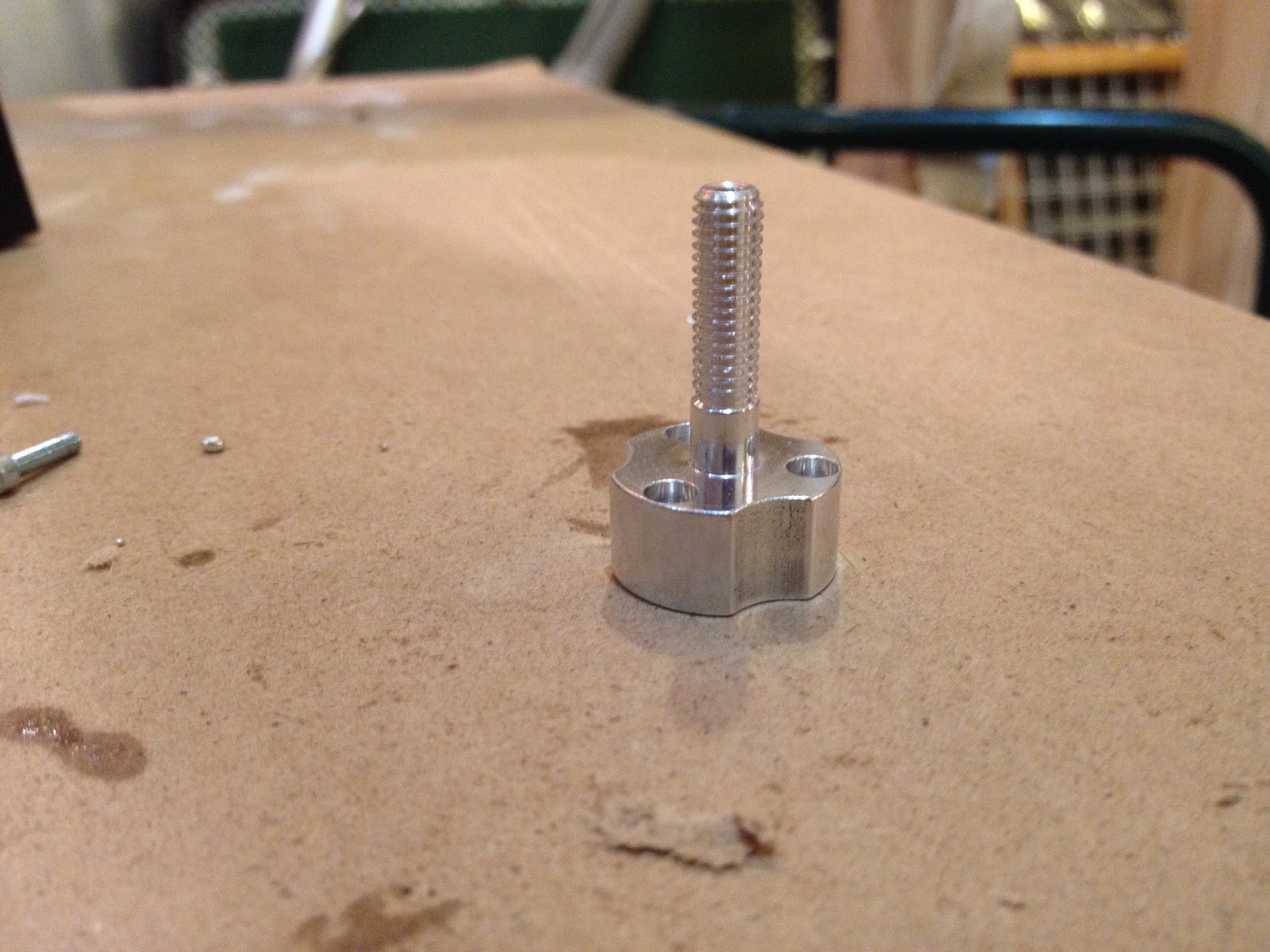
The propellor extensions for the NTM Prop Drive were designed with 10mm rod, threaded for M4 on one end and M5 on the other. These parts were machined at
Porter's Precision Machining in Lewiston, Maine. The M4 end is for attaching the propellor while the 5M end is for the propellor adapter. A CAD image and finished image of our motor, shaft extension, and propellor combination are both below:
 |
| Small Motor w/ Shaft Extension&Prop |
 |
| Prepared NTM 750kv |
Turnigy Aerodrive SK3 – Preparing the Large Thruster
To prepare this motor we also decided to use a propellor adapter (image above), a part that comes with this motor when you purchase it from HobbyKing. This propellor adapter is almost identical to the one used on the NTM series (above).
 |
| Prop Adapter on SK3 |
The shaft extension we designed for this motor was slightly more complicated because of the design of the propellor we're using. Unlike the threaded props we used for the small through-hole thrusters, the large prop for the rear thruster does not come threaded. This meant we had to account for the torque on the prop by adding slots to lock it in place. One end of this shaft is threaded to lock onto the propellor adapter while the other is threaded to fit a lock nut used to hold on the large propellor.
 |
| Prop on Shaft Extension |
 |
| Shaft Extension |
And below is a CAD drawing along with a picture of the prepared Aerodrive SK3:
 |
| Large Motor w/ Shaft Extension&Prop |
 |
| Prepared SK3 |
We also thought a comparison picture of the large thruster and the small vertical/horizontal thrusters would be helpful:
 |
| Thruster Comparison |


No comments:
Post a Comment