Preparation
We used the same LEDs for these units as we discussed in this post. Just as a refresher, these LEDs are 10W 850nm LEDs. The diodes themselves are 7mmx7mm, but we bought the LED mounted to a 20mm diameter start PCB. This PCB makes it easier for us to mount and heat-sink the LED to our custom LED unit.
 |
| LED ENGIN 850nm on Start PCB (Stock Photo) |
To cut out the LED mounts/heat-sinks we used an 1/8" end mill with the Laguna. While cutting the aluminum we had to make sure our feed rate was slow enough so the bit didn't break and that the bit was cooled to ensure clean cutting. For the feed rate we found that 5 inch/minute works the best. We also needed to continually cool the end mill to keep it cutting well. The combination of the feed rate an the WD40 we used for cooling, small bits of a aluminum "sand-castled" around the path of the end mill. Below is a picture of this as well as a short clip of the router cutting our an aluminum heat-sink.
 |
| Cut Aluminum w/ Debris |
After cutting out the aluminum we used a hand drill to make two small holes in the back of each of the LED pockets. These holes are used to both route and organize some of our wire.
 |
| Back of LED |
We then soldered the wires onto the LEDs before mounting them to the aluminum heat-sinks. The first unit we put together we saved the soldering for last. Our heat-sink worked a little too well and made it difficult to heat up the LED enough to solder on the wires. We learned from our mistake though and the second unit we soldered much quicker and cleaner.
Assembly
After preparation we used heat-sink epoxy to attach the back of the start PCBs to the back of the aluminum pockets. After waiting 3 days for the epoxy to fully cure we used a clear epoxy to cover the rest of the PCB and the tops of the wires, which protrude slightly from the pocketed section of our aluminum heat-sink. We made sure to keep the LED lenses clean and to have our epoxy dry flat. Below is an image of the clear epoxy drying over the LEDs. We mounted them in the vice to keep a level surface. If you look close enough you might also be able to see some black – that is where the heat-sink epoxy squeezed up through the star PCB when we epoxied it the first time.
 |
| LED Unit Epoxy Drying |
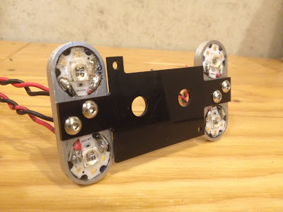
After epoxying the LEDs we used a 4M tap to tap the holes in the middle of the unit. We then mounted the units to the front plate of our camera mount (pictured in green at the end of our camera CAD post).
 |
| LEDs Mounted to Camera Cover |
thanks for sharing valuable article. I would like to see more this kind of informative article. you may also find Waterproof plastic connector USA : Waterproof plastic connector USA
ReplyDelete